
Applicable device: Lixel P1 (PortalCam)
What Are Control Points
Control Points are a core feature added to the Lixel P1 to support multi-map fusion, mainly used to enhance spatial consistency between multiple map segments and improve the stability and accuracy of fusion reconstruction.
Control points apply to the following three fusion scenarios:
| Fusion Scenario | Role of Control Points |
|---|---|
| Map fusion | Spatial alignment of multiple ground scan segments |
| Aerial-ground map fusion | Spatial alignment of ground data and drone data |
| HD Enhancement | Spatial alignment of enhancement images and original scan data |
Placing the Device
When you need to add a control point during capture:
- Open the PortalCam tripod and place the device stably at the location where you want to add a control point
- The control point should be located in a well-lit, texture-rich, unobstructed open area as much as possible
- After placing the device, it is recommended that the operator walk a full loop around the control point area to ensure 360° coverage of the surroundings, which significantly improves fusion algorithm stability
Position Accuracy for Shared Control Points
If a control point needs to be shared between multiple maps (for map fusion), the control point positions only need to be roughly consistent:
| Parameter | Tolerance |
|---|---|
| Distance difference | < 0.5 m |
| Direction difference | ± 20° |
| Height difference | about 10 cm |
Control Point Placement for Different Fusion Scenarios
Map Fusion
| Requirement | Description |
|---|---|
| Quantity | ≥ 3 |
| Distribution | L-shaped distribution |
| Spacing | Distance between each other ≥ 10 m |
| Naming | Same-name control points must have identical names across maps |
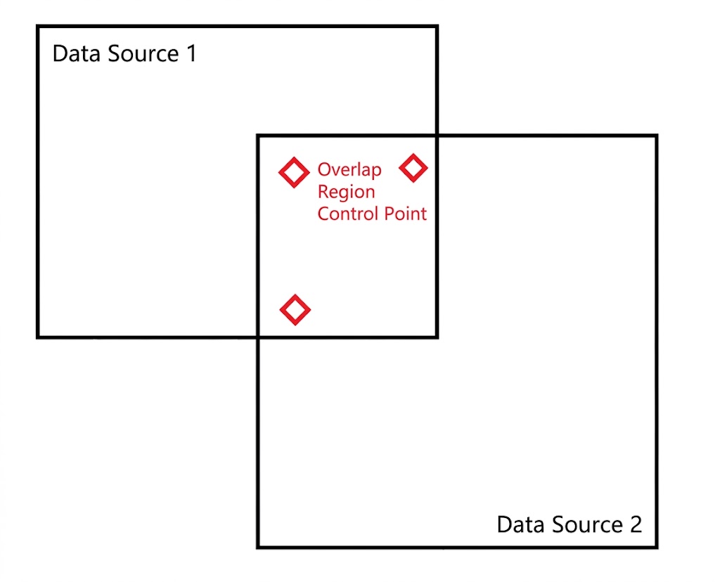
Map fusion control point distribution (L-shaped, ≥3, spacing ≥10 m)
Aerial-Ground Map Fusion
- Control points should be set at the drone takeoff point
- The PortalCam orientation should be consistent with the drone camera direction
- Drone takeoff data must be placed in the same directory
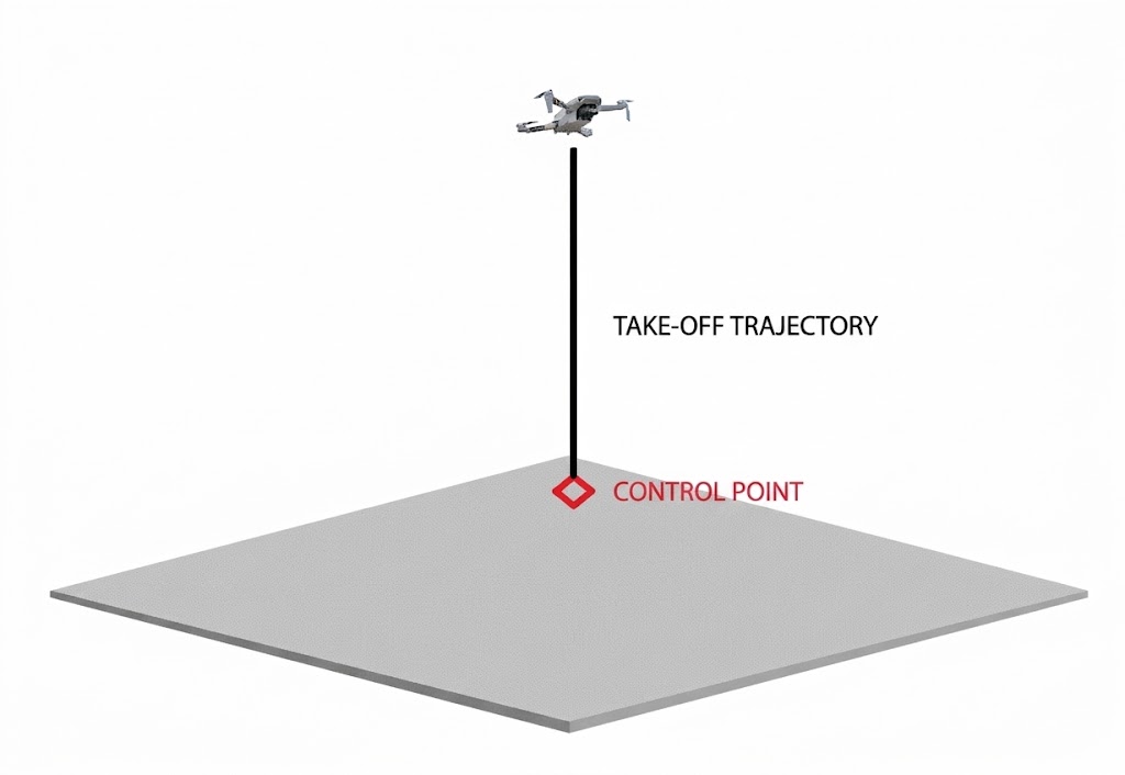
Aerial-ground fusion control point distribution (set at the drone takeoff point)
Example data directory structure:
default_2025-11-02-142755/      # PortalCam project file
├─ project_data/
│  ├─ log/                      # Logs
│  ├─ model/                    # potree model files
│  ├─ photo/                    # Camera photos for the control point
│  ├─ control_points.csv        # Control point information
│  ├─ gnss.csv
│  ├─ poses.csv
│  └─ preview_photo.jpg
└─ 2025-11-02-142755.xbin

Drone/                          # Drone photo files
├─ DJI_202503191521_001/        # Aerial photo folder
│  ├─ image1/
│  ├─ image2/
│  └─ ...
├─ DJI_Link_1/                  # Vertical takeoff/landing photo folder
│  ├─ image1/
│  ├─ image2/
│  └─ ...
└─ ...
HD Enhancement
- Control points should be located in the enhancement area and face the direction to be enhanced
- The first frame of HD Enhancement should start from directly above the control point
- The corresponding enhancement data must also be placed in a single directory
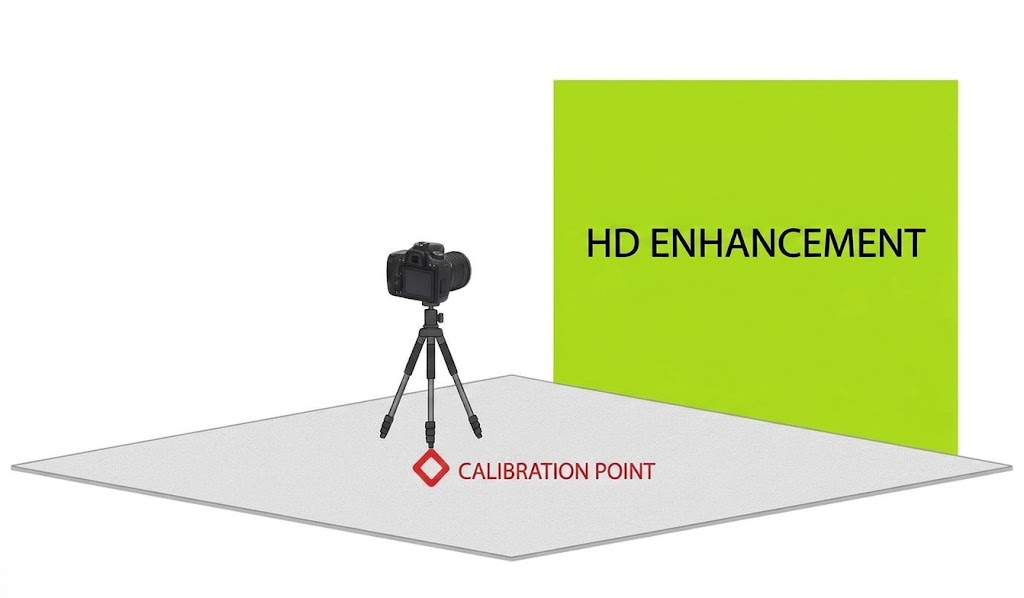
HD Enhancement control point distribution (located in the enhancement area, facing the target)
Adding a Control Point
- After placing the device stably, open the capture interface of the LCC Scan App
- Select the "Add Control Point" function
- Set the control point attributes:
| Attribute | Description |
|---|---|
| Control point number | Automatically generated by the system, unique and non-repeatable |
| Control point type | Map fusion control point / Aerial-ground fusion control point / HD Enhancement control point |
| Control point name | User-defined, used to distinguish same-name points across different maps |
- Select the corresponding control point type based on the actual scenario
- After creation, the system synchronously records position, direction, and other information
⚠️ Note: Do not power off within 5 seconds of adding a control point, to avoid losing the control point file.
Considerations
- Ensure there is no obstruction within the control point's field of view
- Avoid direct strong light on the control point location to reduce positioning error
- Walk a full loop around the control point after placement (360° coverage)
- The position and orientation of same-name control points across different maps should be roughly consistent
